How to Enable GNSS+INS system on K8 series modules
GNSS (Global Navigation Satellite System) is a satellite-based positioning system that provides location and time information anywhere on or near the Earth's surface. Examples of GNSS include GPS, GLONASS, Galileo, and BeiDou.
INS (Inertial Navigation System), on the other hand, is a self-contained navigation system that uses accelerometers and gyroscopes to track the movement of an object. By measuring changes in velocity and direction, INS can calculate an object's current position and trajectory. INS is particularly useful in areas where GNSS signals are weak or unavailable, such as underground or underwater.
In many cases, GNSS and INS are used together to provide a more accurate and reliable navigation solution. This is known as integrated navigation or GNSS/INS integration. ComNav K8-series combines the strengths of both systems, integrated navigation can be robust in challenging environments and provides continuous positioning even during short GNSS outages, here are some examples of K8 GNSS+INS performance in different environments.
Green: GNSS only Red: GNSS+INS

Under overpass

Through subway station

In the garage
 Installation and setup
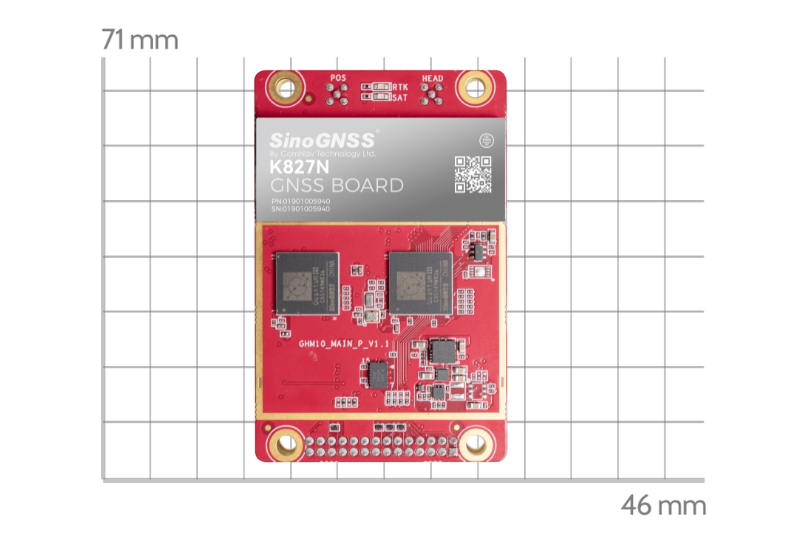
Install the board on the vehicle as rigidly as possible to ensure that the board and the vehicle will not move relative to each other during driving. The device also needs to be installed in a location that minimizes the impact of vibration and electromagnetic interference.
After installation, you can active the INS option as commands
Inscontrol enable set smootheddr on saveconfig | //activate INS mode //activate the INS smooth mode // Save configuration |
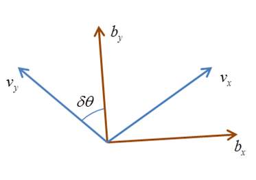
It is recommended that the Y-axis marked on the module be kept on the same straight line as the direction of the carrier body, that is, Y-axis points to the forward direction of the vehicle. For different direction of installation, you can refer to below chart to setup the imuaxestype with command below.
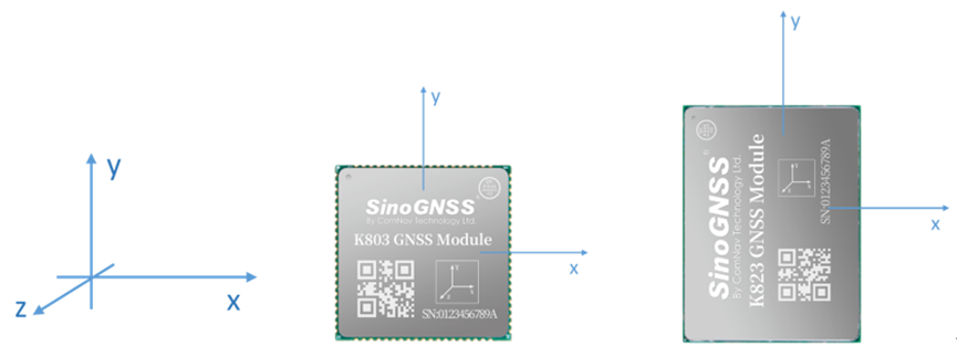
INS coordinate system
set imuaxestype <axestype> saveconfig | //Set axes of OEM module // Save configuration |
Axestype | Description |
1 | The front of the OEM module faces up, the y-axis faces the front of the vehicle. |
2 | Axes 1 rotates 90 degrees counterclockwise horizontally. |
3 | Axes 1 rotates 180 degrees counterclockwise horizontally. |
4 | Axes 1 rotates 270 degrees counterclockwise horizontally. |
5 | The front of the K8 module faces down, the y-axis faces the front of the vehicle. |
6 | Axes 5 rotates 90 degrees counterclockwise horizontally. |
7 | Axes 5 rotates 180 degrees counterclockwise horizontally. |
8 | Axes 5 rotates 270 degrees counterclockwise horizontally. |
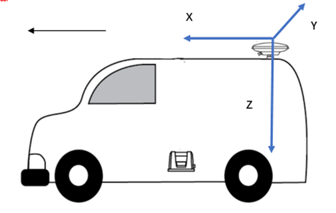
Drleverarm value: the three-axis vector from the antenna phase center to the INS phase center.
set drleverarm X Y Z saveconfig | //set arm value (-20m~+20m) // Save configuration |
Note: The XYZ is not related to the axis of INS. X points to the front of the vehicle, Y points to the right of the vehicle, and Z points downward.
Once change the above INS configuration, it will need “reset” to board to save the INS configuration.
INS Initialization
The inertial navigation system (INS) calculates the navigation result by integrating the measurement value of the inertial sensor, that is, each iteration of the navigation equation needs to use the previous navigation parameters such as position, velocity, and attitude as its initial value. Therefore, before using INS to provide navigation results, it must be initialized.
Method: After enable INS, there will need firstly get correction input to get RTK fixed solution, and then drive the vehicle to an open environment, and make sure the speed reaches the initialization threshold, and drive about 10m to complete the initialization.
INS Calibration
In order to ensure the performance of INS, it needs to be calibrated after the initialization is completed to eliminate the placement error of the INS equipment.
Method: Keep a speed of 5m/s in an open environment and drive in a straight line for at least 200m, turn 90° for left and right twice for each (with a good road environment, you can turn around in a figure 8).
The status of calibration can be checked by message “sysrts”. After calibrated, the status of INS will be “3”.
Log sysrts | //check INS status |
Here is an sample output of SYSRTS message:
$SYSRTS,466724.10,093826.10,48,5,,AT,41,78,1,1,49,,,,,,,,,M,AIR,0,,42.5,3,9,2200,0,0*3A
There are totally 4 different types of status for INS, as the below table lists:
INS status | INS enabled | INS initialized | INS Calibrated |
0 | û |
|
|
1 | ü |
|
|
2 | ü | ü |
|
3 | ü | ü | ü |
Positioning and heading message
Request positioning and heading message with GPGGA message and GPTRA message.
log gpgga ontime 0.2 log gptra ontime 0.2 | //positioning message //heading message |
In GPGGA message, the solution status for GNSS+INS is “6”; In GPTRA message, the solution status for GNSS+INS is “6”.
Example of GPGGA message
$GPGGA,024941.00,3110.4693903,N,12123.2621695,E,6,16,0.6,57.0924,M,0.000,M,99,AAAA*55
Field# | Structure | Description | Symbol | Example |
1 | $GPGGA | Log header |
| $GPGGA |
2 | utc | UTC time of position (hours/minutes/seconds/ decimal seconds) | hhmmss.ss | 202134.00 |
3 | lat | Latitude (DDmm.mm) | llll.lllllll | 3110.4693903 |
4 | latdir | Latitude direction (N = North, S = South) | a | N |
5 | lon | Longitude (DDDmm.mm) | yyyyy.yyyyyyy | 121232621695 |
6 | londir | Longitude direction (E = East, W = West) | a | W |
7 | GPS qual | GPS Quality indicator 0 = fix not available or invalid 1 = GPS fix 2 = SBAS, C/A differential GPS, OmniSTAR HP, OmniSTAR XP, OmniSTAR VBS, or CDGPS 4 = RTK fixed ambiguity solution (RT2) 5 = RTK floating ambiguity solution (RT20), OmniSTAR HP or OmniSTAR XP 6 = Dead reckoning mode (GNSS+INS) 7 = Manual input mode (fixed position) 15 = PPP | x | 1 |
Example of GPTRA message
$GPTRA,063027.30,101.78,071.19,-00.00,6,10,0.00,0004*51
Field# | Structure | Description | Symbol | Example |
1 | $GPTRA | Log header |
| $GPTRA |
2 | utc | UTC of position | hhmmss.ss | 063027.30 |
3 | heading | 0 ~ 360 degree | hhh.hh | 101.78 |
4 | pitch | -90 ~ 90 degree | ppp.pp | 071.19 |
5 | roll | [Reserved] | rrr.rr | -00.00 |
6 | sol status | solution indicator 0 = fix not available or invalid 1 = Single point position 2 = SBAS, C/A differential GPS, OmniSTAR HP, OmniSTAR XP, OmniSTAR VBS, or CDGPS 4 = RTK fixed ambiguity solution (RT2) 5 = RTK floating ambiguity solution (RT20), OmniSTAR HP or OmniSTAR XP 6 = Dead reckoning mode (GNSS+INS) | I | 4 |
About ComNav Technology
ComNav Technology develops and manufactures GNSS OEM boards and receivers for high precision positioning demanded applications. Its technology already been used in a wide range of applications such as surveying, construction, machine control, agriculture, intelligent transportation, precise timing, deformation monitoring, unmanned system. With a team dedicated for the GNSS technology, ComNav Technology is trying its best to supply reliable and competitive products to worldwide customers. ComNav Technology has been listed on the Shanghai Stock Exchange (Science and Technology Board), securities :ComNav Technology (Compass Navigation), Stock code: 688592.
About SinoGNSS®
SinoGNSS® is the official trademark of ComNav Technology Ltd., registered in People's Republic of China, EU, USA and Canada. All other trademarks are the property of their respective owners.